Bsides Charleston SAO Assembly
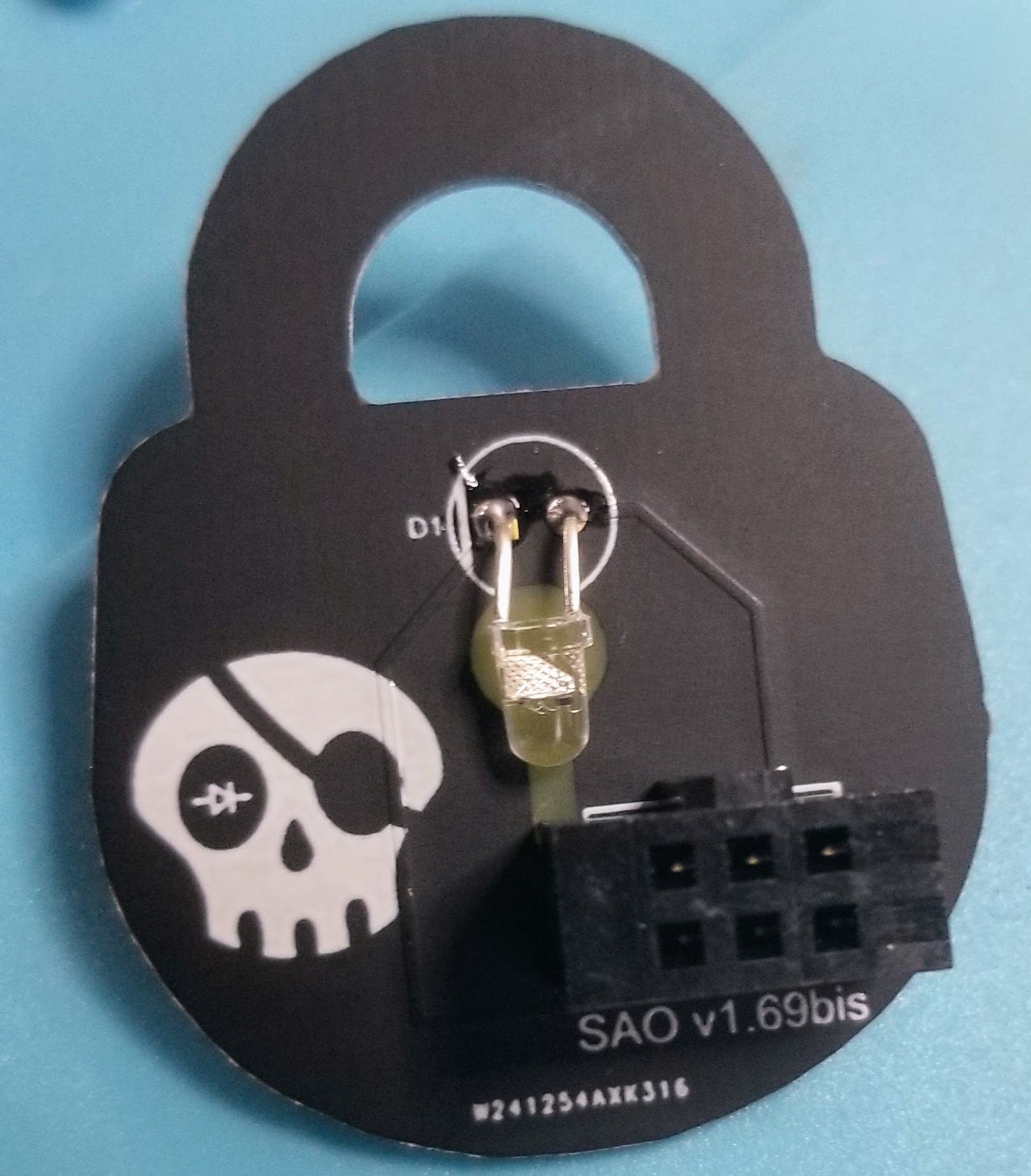
So you have acquired one of the Bsides Charleston Lock SAO’s and discovered its just a kit and are wondering now what do you do? Fear not, we have your back. We will assume you have basic soldering skills.
![]()
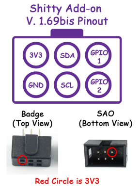
There are only two things you have to keep in mind as you are assembling that can cause you problems. The first is to get your LED inserted correctly. LED’s have polarity and need to be inserted in the correct orientation or they will not work (damn diodes). The second is the orientation of the headers on the SAO and badge. We have provided the ‘keyed’ headers so as long as you keep them with the ‘key’ on top for both the badge and SAO you will be fine.
 s
s
Let’s get started
First up is the LED. LED’s have polarity (+/-) as earlier mentioned with the positive pin being the anode or longer pin, and the cathode as the negative pin. On most LED’s, there is a ‘flat’ side as well which indicates the cathode. You can see on the PCB a line going through the circle that indicates the cathode.
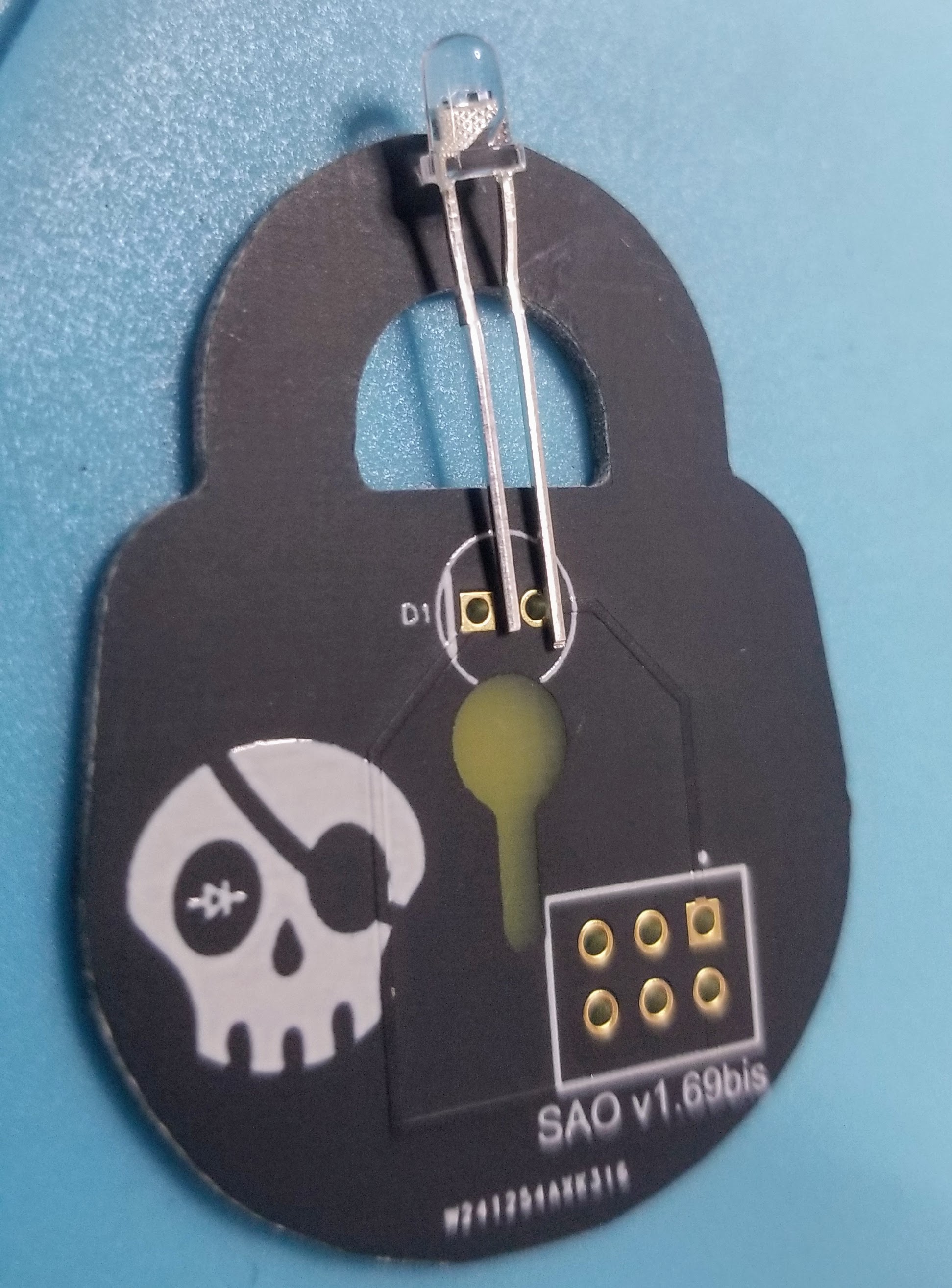
The best way to install through hole LED’s is to put the pins through and then splay them out so that it stays in place while you solder it. You will want to bend the LED down so that the top of it stays close inside the circle to get the optimum effect (a bit higher than shown in the picture at the end).
You can solder the pins of the LED on the front or backside of the PCB and it will not make any difference.
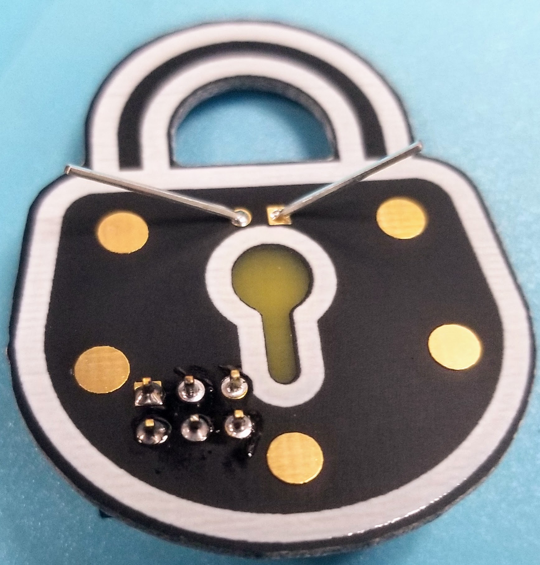
The final step is to solder on the SAO connector headers on both the badge and SAO as shown below keeping in mind the correct orientation as discussed before.
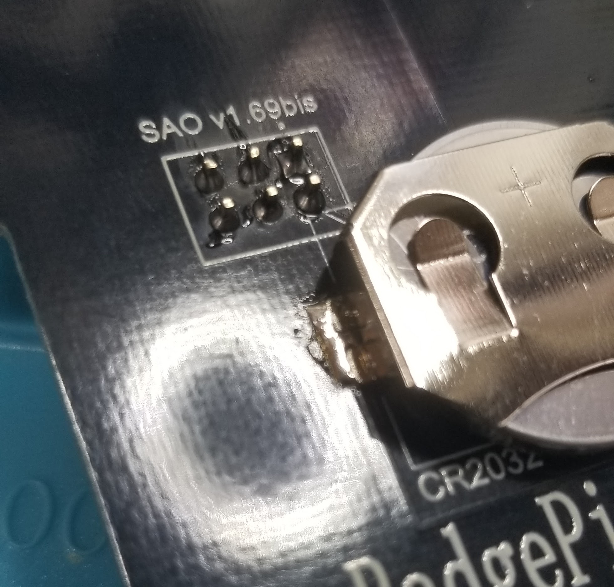
![]()